
Injection Moulding
Injection Moulding Principles
For thermoplastics the dominant process for producing complex shapes is injection moulding in which the polymer melt is produced efficiently in one part of the machine.
In a separate function, the measured volume of melt is then forced into the cavity between the two mould plates. These are locked together to prevent separation under the high hydrostatic pressure of the melt in the cavity.
The final stage is to extract heat from the moulding using a heat exchange system incorporated into the mould plates, before the mould halves are opened and the finished moulding ejected. For thin walled parts cycle times can be less than 10 seconds but for thicker sections the cycle times may be well over 60 seconds.
Melt temperatures can be as low as 150oC but for some thermoplastics they have to be over 350oC. In all cases injection pressures can be up to 120 MPa, consequently creating large hydrostatic opening forces in the mould.
Mould locking (clamping) forces can be as low as 100 kN (10 tonnes force) for small area mouldings and more than 25,000 kN (2500 tonnes) for very large mouldings.
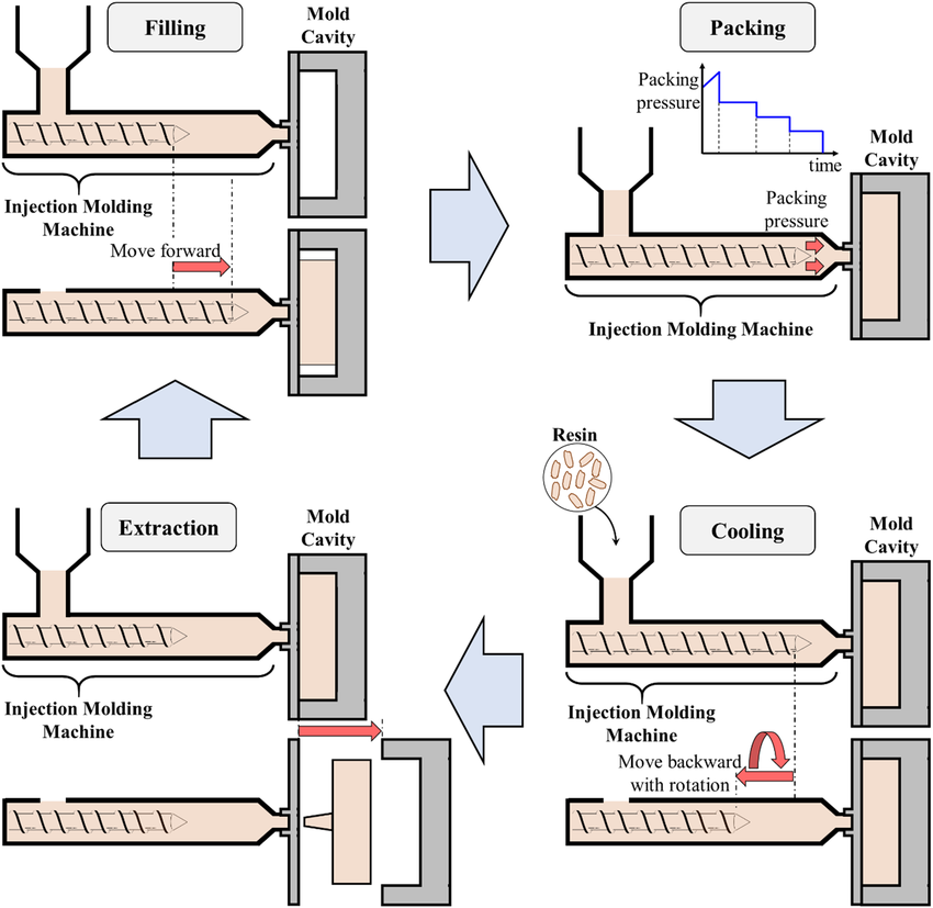
The injection moulding process can be conveniently divided into four phases.
To keep the cycle time short, some of these phases can operate in parallel, eg plasticisation for the next cycle can occur at the same time as cooling and ejection.
To optimise the filling process injection times are short (less than 5 seconds and sometimes less than 1 second). This accounts for the high injection pressures (up to 120 MPa).
As soon as the melt starts to cool in the cavity it will contract and lose compression. Volumetric shrinkage during the cooling phase will result in a moulding that will be slightly smaller than the mould cavity and lacking the detail of the mould cavity.
To minimise the mould shrinkage effect, pressure is maintained for a few seconds after the injection stage to pump more melt in to compensate for the shrinkage.
A high hold pressure will also minimise mould shrinkage but it cannot be eliminated. Typical mould shrinkage values range from 0.5% or less for amorphous thermoplastics and filled thermoplastics to more than 1% for semi-crystalline thermoplastics.
To meet dimensional specifications mould cavity dimensions have to be adjusted to allow for the shrinkage. Because the final mould shrinkage value depends on process variables such as melt temperature, injection pressure, hold pressure and hold time, this presents a major problem to toolmakers to anticipate the shrinkage factor.
Machine Design
Plasticiation Unit
Originally plasticisation units were designed with plungers that pushed granules from a hopper, through a heated cylinder to melt the thermoplastic and forced the melt through a nozzle and feed channel into the mould cavity.
The inefficient plunger design was eventually replaced by the in-line screw design. Here plasticisation is achieved by the rotation of an archimedean screw in a heated cylinder, using shear heating more than conduction heating to give a more homogeneous melt.
The melt collecting at the head of the screw forces the screw back on its axis (while still rotating) until the required volume of melt has been produced.
Screw rotation is stopped and a hydraulic cylinder brings the screw forward in a plunger action to fill the mould cavity. By separating the plasticisation and injection stages efficiency and also quality are greatly increased

Mould Unit
The function of the mould unit is to:
locate the two mould halves without warping and misalignment;
open and close the parts of the mould;
lock the mould halves together during injection;
assist in ejecting the mouldings when the mould opens;
assist cooling of the moulding before ejection.
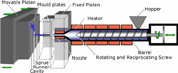
To minimise mould distortion, misalignment and warping the mould plates are mounted on large steel plates (platens). These are aligned with a series of tie bars (two for very small machines and 4 for larger machines).
Most designs consist of 3 platens, the fixed platen (next to the plasticisation unit), a tail stock and a moving platen in between, running on the tie bars to effect the opening and closing strokes. One mould plate is secured to the fixed platen and the other mould plate to the moving platen.
During the injection, pressure-hold and cooling phases the mould plates must be locked together by a force that exceeds the mould opening force created by the hydrostatic pressure of the melt in the cavity and the effective area of the mould cavity (projected area).
In some machines the locking force is generated by a hydraulic cylinder between the tail stock and the moving platen (direct hydraulic)
In other designs (toggle) a system of levers provide rigid beams to counteract the mould opening force in the mould-closed position but also provides rapid opening and closing actions with the aid of small hydraulic cylinders.
Configuration
Although the majority of injection moulding machines are designed with horizontal plasticisation units and in-line, horizontally opening mould units there are other possible configurations.
Horizontal plasticisation, vertical mould unit
Vertical plasticisation, horizontal mould unit
Vertical plasticisation, vertical mould unit
Horizontal plasticisation, horizontal mould unit opening at 90o