Extrusion
Extrusion is a process in which polymeric materials, in the form of powder, granules, trip or melt, are converted into products of controlled cross-section in a continuous fashion. This is achieved by softening (plasticising) the material using heat and/or pressure, forcing the softened material through and orifice (die) and maintaining the desired cross-section by cooling or by chemical reaction.
Extruder Design
Ram Extruder
In its simplest form an extruder is analogous to icing a cake. The polymer is fed to the cylinder (barrel) in a plasticised state. The cylinder is heated to maintain the softened state.
A hydraulically actuated ram (plunger) forces the material through a die clamped to the end of the cylinder. A ram extruder is not truly continuous. However, it is appropriate for short product lengths, eg strip for tyre tread. Also the temperature distribution, and hence viscosity distribution, is poor.
Gear Pump Extruder
Gear Pump mechanisms, meshing cogs, work well on pre-plasticised , low viscosity materials, giving a positive throughput. However, they are poor for plasticising. Gear pumps are now used between a single screw extruder and the die to maintain constant throughput.
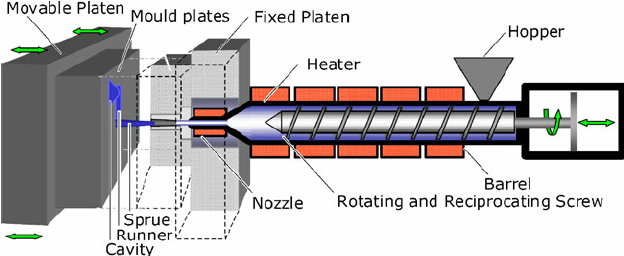
Single Screw Extruder
A rotating Archimedean screw in a cylinder ensures the continuous transfer of material from the feed (hopper) end to the die end. Heat is supplied from external heater bands or jackets.
With a simple screw design the conducted heat sets up unwelcome temperature gradients in the material. A long cylinder would be required for operating at a reasonable throughput.
The limiting factor would be the length of the screw which is restricted by the drive torque it can sustain. On smaller extruders (35 mm diameter screw) length/diameter (L/D) ratios go up to 35:1 but on larger extruders (200 mm diameter) L/D ratios approach 40:1.
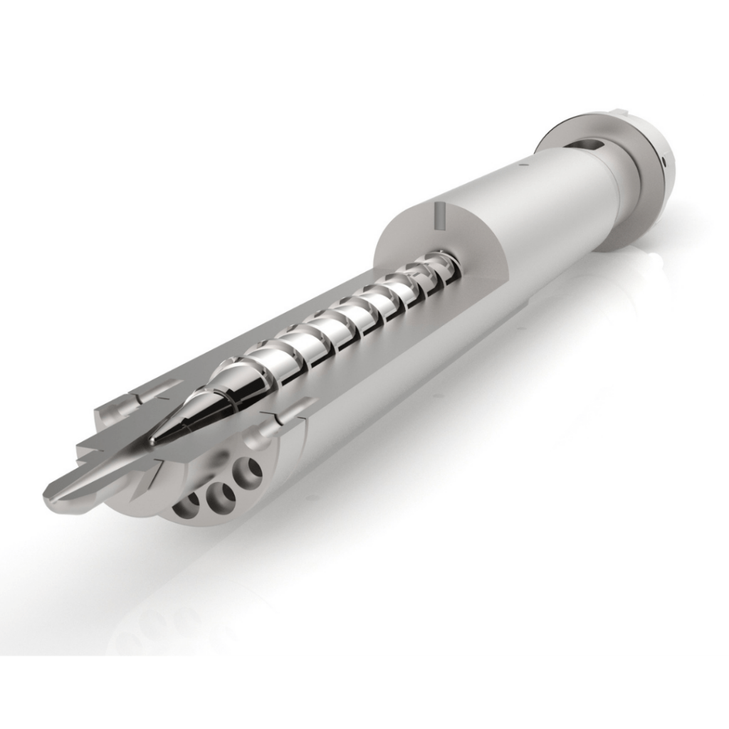
Screw Design
To maximise the heat input and also to produce more uniform temperatures, frictional (shear) heating, generated between the rotating screw and the stationary cylinder, is maximised by putting the material under pressure. The compression is achieved by reducing the available volume (flight volume) along the screw by progressively increasing the root diameter of the screw.
For design and operational purposes, the screw can be divided into three zones:
Screws are normally constructed from hard tool steel with hard wearing flight tips. However, they are still subject to wear and require refurbishing at intervals. Some screws have internal water cooling to assist the feed mechanism in the feed zone and to also aid the shear heating process.

Extruder Cylinder
Because of the high pressures experienced during plasticisation the cylinder must be of strong construction. Hardened steel liners are used to minimise wear and the cost of replacing the complete cylinder.
For easily softened materials (e.g. elastomers) steam or hot oil jackets are sufficient but for thermoplastics cylinder heating is normally provided by banks of electrical resistance heaters.
Where shear heating is very efficient, cooling channels or aluminium fins with air blowers are used to take away excess heat.
At the feed end the hopper should be designed to give a positive flow of granules to the throat of the extruder. Magnets in the hopper prevent metal contamination from reaching and damaging the screw.
For materials that absorb moisture (e.g. polyamides) it is important to pre-dry the material. This can be done either off-line or with hopper dryers that circulate warm dry air.
Vacuum hoppers remove air from powder feed and prevent blocking (bridging). The level of material in the hopper can be automatically maintained using pneumatic filling devices from bags, bulk containers or silos.
Dosing devices for mixing virgin polymer with masterbatch or recycled regrind can also be incorporated into the hopper.
At the delivery end there is a flange to which is located the die, by screw fixtures, bolts or quick release mechanisms for die change and maintenance.
Screw Drive
Electric motors (either AC or DC) are used for screw rotation, normally with gear reduction and drive belts to give a range of screw speeds. Modern extruders have infinitely variable screw speeds. The high pressures created at the die end will tend to force the screw back on its axis and thrust plates or tapered roller bearings are incorporated to prevent backward movement.
. Die Design
The function of an extruder die is to:
produce the required extrudate cross-section;
break up the rotational flow coming from the extruder
maintain laminar flow to the die exit
ensure consistent and minimal residence time of melt in the die
make allowance for die swell
maintain the melt temperature
Breaker Plate/Screen Pack
To break up the rotational flow coming from the extruder cylinder and also to establish laminar flow, a perforated plate (breaker plate) is inserted between the extruder cylinder and the die.
The breaker plate also helps to filter out unmolten granules and contamination as well as increasing the back pressure in the cylinder. Therefore, this results in more efficient plasticisation.
The filtering function and back pressure effect is enhanced by placing layers of fine wire mesh (screen pack) behind the breaker plate. Screen packs have to be changed (sometimes with automated systems, to maintain process conditions.
Die Head
Within the die bodies, laminar flow of the melt is maintained by avoiding dead spots and abrupt changes of sections. Most dies are designed with converging sections to increase the pressure before the die exit.
In the final section (die parallel or die land) cross-sections are maintained constant to minimise die swell. Dies normally have some form of external heating to maintain melt temperatures. Higher die temperatures at the die exit can produce a better finish on the extrudate and minimise other extrusion faults.
Die Swell
When a viscoelastic polymer melt is subjected to shear or extensional stresses in the die, there is an elastic recovery (memory) in the extrusion direction after the extrudate exits the die.
This elastic recovery manifests itself as a contraction on the length (not visible in a continuous process) and a corresponding expansion in the cross-section, producing an extrudate with cross-sectional dimensions greater than the dimensions of the die exit.
Die swell can vary from 10% to more than 100% increase in dimensions. It depends on the material, melt temperature, extrusion speed and also die geometry.
Die swell can be minimised by increasing the length of the die land, increasing the melt temperature and also by reducing the die throughput (decreasing screw speed)
Types of Dies
Dies vary in design, size and also in complexity to produce a wide range of extruded products.

Solid section Dies
To produce rod, edging strip, curtain rail and window frame profiles, dies have a simple design with a tapering entry to the die exit and a long land length (at least 10 times the cross-section dimension)
Hollow Section Dies
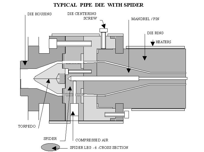
To produce tubing or pipe, dies are designed with an internal mandrel (torpedo) to create the internal dimensions. The complexity arises from the method of locating the mandrel within the die head to allow for concentricity adjustments and also to minimise flow disruption.
In some cases the mandrel is mounted on three small legs (spiders) in a straight through die. Sometimes it is mounted more rigidly in the die head, in a crosshead die where the melt has to sweep round the mandrel and turn through 90o to the die exit.
In both cases there will be weld line weaknesses in the extrudate where the melt flow is recombined. A further complication in hollow dies is that there has to be an internal pressure in the extrudate during cooling to prevent the hollow extrudate collapsing.
This is normally achieved by an air line through the mandrel via one of the spider legs. However, a more elegant solution is to apply an external vacuum to the extrudate as it is cooling.
Wire Coating Dies
With a cross-head die it is possible to feed a substrate, such as a wire conductor, through a hollow mandrel so that the substrate accepts a continuous coating of polymer melt in the die-head.
Dies can be designed to give a constant wall thickness of coating (tubing or sheathing dies) or to produce a product of constant outer diameter (in-filling dies).
In the wire and cable industry, in-filling dies are normally used for primary insulation and tubing dies for

Sheet and Film Dies
To produce flat section products of varying width, slit dies have been developed to produce film and sheet up to and over 2 m wide and thicknesses down to 100 µm. Fish tail designs, with gradually increasing width and reducing height, have problems in distributing melt to the edges.
Incorporating manifold channels into the die encourages more uniform flow (coathanger die). Restrictor bars are adjusted across the width for fine control of sheet thickness.
In biaxial stretch film manufacture extruded sheet, while still hot, is stretched in the length and in the cross-direction. This gives very wide (14 m) and very thin (less than 100 µm) film for packaging.

Tubular Film Dies
Annular cross-section dies produce thin walled tubing with uniform thickness. By stretching the hot tube circumferentially and stretching the tube in the length the diameter is increased and the thickness reduced. Slitting the tube in the length produces very wide film.
Alternatively cutting and heat sealing the tubular film is a simple method of manufacturing polyethylene bags and sacks.

Co-extrusion Dies
Thermoplastic sheet and packaging films can be produced in co-extrusion dies (slit dies or tubular dies) consisting of individual layers of different polymers bonded together.
The different melt streams, prepared in separate extruders, are brought together either at the die exit or at an earlier stage in the manifold. The key to co-extrusion lies in the laminar flow of thermoplastic melts, with no tendency for mixing between successive layers
Downstream Equipment
The success of manufacture using the extrusion lies as much in the design and operation of the rest of the production as in the extruder and die.
Cooling of extruded products is achieved using air, water bath and contact with cold metal rollers. During the cooling process the dimensions of the extrudate have to be maintained or, in some cases, modified to meet the product specification.
Calibration takes the form metal plates, calibration dies, or rollers. Extrusion is a continuous process. However. products are normally cut to lengths (over 100 m for flexible products but less than 1 m for rigid extrudates).
Extrudates are automatically cut to length using guillotine action, cutter wheels or saws. Flexible film is wound on a roller, again with automated roll change.
Other downstream equipment includes edge trim, lamination, embossing, printing and also on-line quality checks (eg thickness profile, pinholes)